
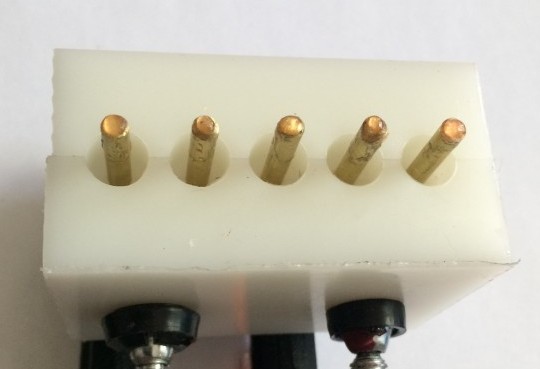
In Part 10 of my series on the making of the Wall-Saver safety cylinder, I talked about how I finally arrived at a successful production method for the main cylinder body. But as I had mentioned in part 5, there was still the issue of plastic inserts to hold the brass cores against the springs. Glue experiments had failed, which left ridges (common on commercially available snap caps). The cylinders were already being molded with ridges in them, so it was a matter of making ridged plastic inserts to fit them.

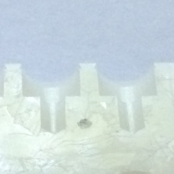
As I mentioned back in Part 5, the first attempt to do this was by taking silicone castings of the actual cylinders, and using those castings as mold masters (actually, the very first attempt used plastic rods with holes drilled down the center as mold masters, but as there was no easy way to add a ridge to them, that didn’t work for the new plan). This did yield some somewhat useable results, but with two major problems. First, shrinkage again. The new inserts were at least 1% smaller than the cylinder from which they were made, which was a problem when tolerances stacked up wrong. Second, because the mold master were themselves squishy rubber—two of the five mold cavities made from the first set were deformed and useless.
It was therefore necessary to make rigid molds. But that creates its own problem—while silicone can be deformed to extract a cast part, the rigid molds would have to have a parting line. And that parting line would have to occur around the largest circumference to avoid undercuts. That meant a pretty
precise machining job on two separate halves that must mate perfectly. It also meant machining a rod through the center of the cavity and then somehow pushing cured plastic off that rod without damaging the part or the mold.
It was too tall of an order, so I didn’t do it. Instead, I designed a mold that parted from the sides and used a rod inserted down the middle to form the hole for the brass.
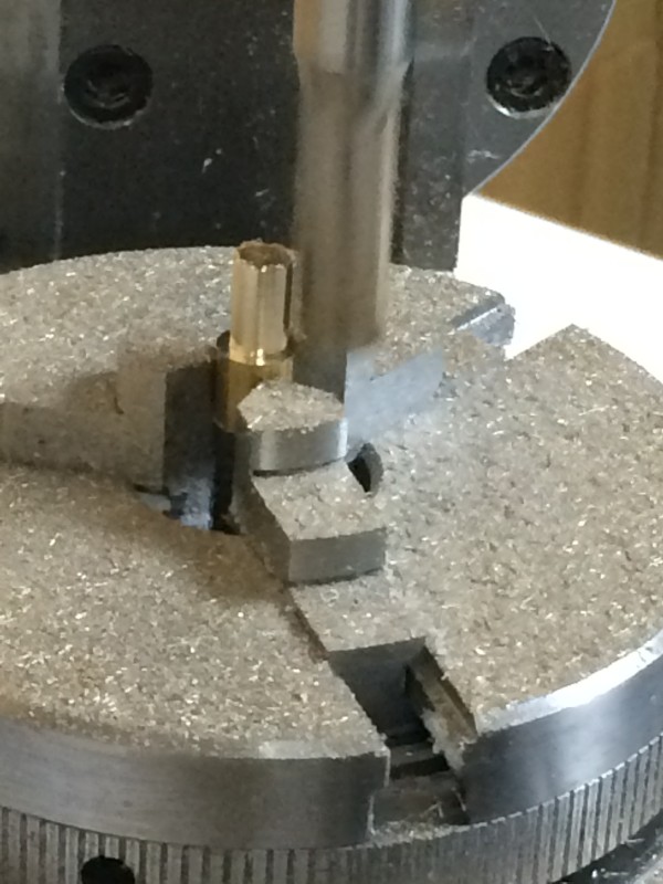
At first, I was aiming for a 5/32” rod and 5/32” brass. But the plastic rods I bought weren’t quite that big, and due to tool/machine/workpiece flex, cutting the brass to exactly that size on the mill wasn’t working either. I had to drill out the plastic inserts to make it work. But considering I was already machining the insert faces, the extra step of drilling (which required some precision) was more than I wanted to do. So I switched to 4 mm brass rods as mold cores (just over 5/32”) and I changed the toolpath to make the brass plungers slightly smaller, and it came together. Working with a dull endmill still caused some oversized brass, but for the most part, it worked.
Leave a Reply