
In Part 3 of my series on the making of Pocket-Safe hammer shrouds, I showed you the first truly functional prototypes off of my thermoformer. The ability to do tiny prototype runs of just a few shrouds—or even just 1, if I wanted—at the cost of just a small sheet of plastic, was huge. It meant I could change things as much as I needed to get things right.
While the decision to go with thermoforming was not only right, but absolutely essential, in this post we see my second big mistake in this process (the first being to design an open-topped, injection-molded part). I wanted to make the sides of the shroud come down and drape over the back of the revolver—to sort of grip the sides a little bit. Not only does that look nicer than something just hanging off the tip of the hammer spur, it also helps the shroud to stay in place by resisting sideward motion. You can’t tell how something might get bumped in your pocket or a holster or attached to body armor, so a bit more grip (but without making it tighter around the hammer spur and therefore harder to remove) seemed like a good idea.
But I was penny-wise and pound-foolish. Instead of paying to do it right, I cut up some Alumalite castings of the shroud die and the back of my 360 PD and I glued them together:

I figured doing that would save me paying to create a CAD model of the back of the gun, but give a nice tight fit because, after all, I was using a direct casting of it, so the dimensions should be very close to exact.
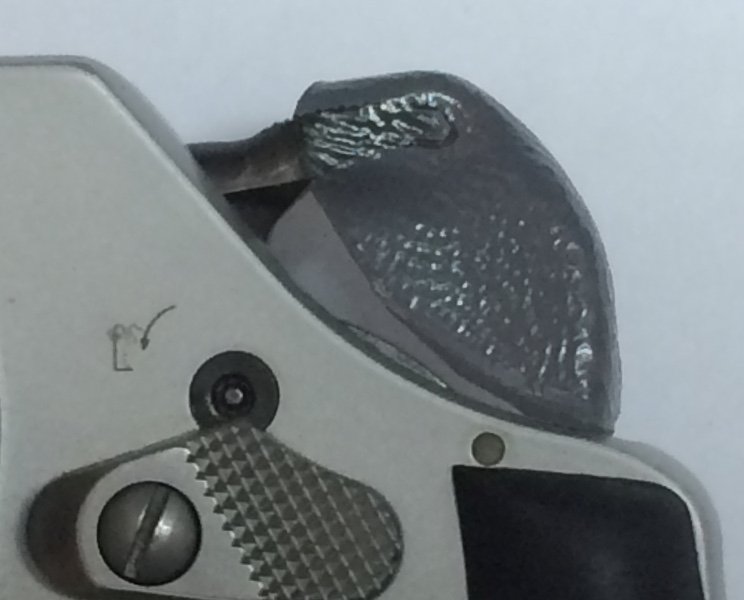
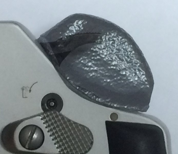
Well, in doing it, I got the angle wrong. The spur of the hammer is meant to slip into the gap between the top of the shroud and the “pinch” below it. It gets caught between them, so that the checkering on the hammer spur prevents it from slipping off, but when the trigger is pulled, the spur forces the “pinch” apart as it comes back, allowing the shroud to slip off. Since I had to cut the hammer off the casting and use sandpaper to approximate the shape well enough to make it all stick together, I actually got the angle WAY off. Have a look.
Rather than slipping into that gap, the hammer spur was forced by the shape to pass through the pinch at an angle. There’s just a little zone of contact, and that friction does all the work. If the shroud gets displaced in the original design, it tends to be pushed back into place by the pinch. If it gets displaced in the erroneous version, there’s no force to push it back. It just stays displaced.
When the first of the new prototypes came off the machine, they still still worked, sort of. Well enough that I overlooked my mistake. I was right that I got a pretty good fit to the back of the gun, but at the expense of the shroud actually functioning the way I had designed it. But again, it worked well enough that the alarm bells didn’t go off in my head.
Now I needed a way to cut the shrouds out that was quicker and also more aesthetically pleasing than heavy shears. Club Workshop had just what I needed: a laser cutter.
Leave a Reply